The Pi attenuation converter allows you to calculate the resistor values for a Pi type attenuation network from a desired attenuation and a system impedance. This tool is used to match signal levels in RF circuits while maintaining the characteristic impedance of the system.
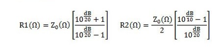
Formula
K = 10^(A / 20)
R1 (shunt) = Z₀ × (K + 1) / (K – 1)
R2 (series) = Z₀ × (K² – 1) / (2 × K)
Explanation of the formula
The constant K represents the linear attenuation factor derived from the value in dB. R1 is the parallel resistance located at the ends of the network, while R2 is the series resistance at the center. These calculations ensure that the desired attenuation is achieved without changing the system impedance.
Uses
- Design of attenuation networks for RF or microwave circuits.
- Precise signal power reduction while maintaining impedance matching.
- Applications in amplifiers, filters and transmission lines.
- Rapid evaluation and simulation of the resistances needed to achieve specific attenuation.